General Concepts:
The purpose of the grid board is to present an accurate array of black lines on a white background. A primary requirement of the grid is to present a constant area cell to the camera and this can most easily be accomplished by positioning the grid so it is perpendicular to the central reflected light ray. In the previous version this was usually achieved by focusing the camera through a central hole in a flexible printed grid that was parallel to the sample. This flexible grid that was stretched within a rigid framework had obvious advantages in space utilization, but was difficult to keep flat with good accuracy. Nearly all early grids used a 50 mm square pattern. A few installations used a rigid grid board. The latest software can work with a grid as small as 12 mm but the optimum trade off between speed and accuracy may be found at 25 mm.
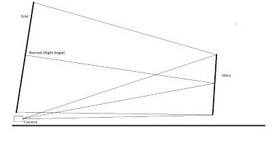 The latest approach is to use a rigid board that is tilted to retain the requirement of light
rays being perpendicular to it. This allows the cell areas to be uniform with
the only downside being the cell positioning on the sample having a
trapezoidal shape. This eliminates the need to position the camera behind a
hole in the grid. The optimum distance between the sample and grid is
approximately 4 meters. This distance enters into the distortion calculation so
is a part of the software configuration in the options menu.
The latest approach is to use a rigid board that is tilted to retain the requirement of light
rays being perpendicular to it. This allows the cell areas to be uniform with
the only downside being the cell positioning on the sample having a
trapezoidal shape. This eliminates the need to position the camera behind a
hole in the grid. The optimum distance between the sample and grid is
approximately 4 meters. This distance enters into the distortion calculation so
is a part of the software configuration in the options menu.
Lighting:
Lighting is a very important consideration in the grid board setup. Sufficient illumination is needed to allow a high contrast image to be taken. The most common fixture is an inexpensive halogen shop light array, or now more prevalently an LED equivalent. A major consideration is the prevention of reflections or glare in the final image. The best general layout seems to have the lighting at the sides or overhead pointed at the grid at about a 45 degree angle. Establishing the best lighting layout is often the largest initial source of problems. Reflections from existing overhead lighting may need to be shielded by baffels or curtains.
Accuracy:
The latest software has the capacity to measure reflected gridline positions to subpixel resolution which translates to fractions of a mm at the grid. This is obviously a strict requirement on the production of a grid board, especially in larger sizes. Remember, the grid board must be at least twice the size of the largest sample to be tested. This condition is less critical in the transmitted distortion case as a method is built into the software to create a master calibration image and then measure only the changes when the sample is inserted. This is more difficult in the reflected case since a perfect mirror would be required to replace the sample during the calibration process.
Sample Support:
The sample is located on a fixture that resembles the typical packing buck found in glass facilities. Its only requirement is to provide a repeatable positioning with the sample at a few degrees from vertical such that the reflection is centered on the grid.